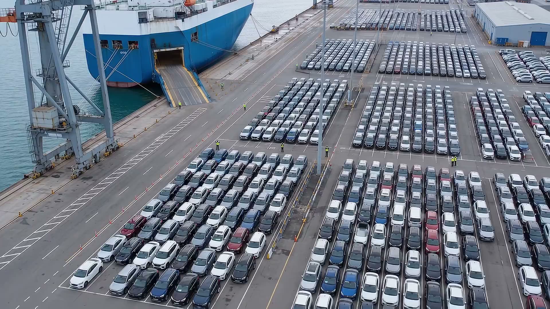
Aerial view of the vehicle storage yard and a RoRo vessel at berth
Operational playbook

RoRo Operation
Discharge Plan

5,000 vehicles in 20 operating hours

Step-by-step control from pre-arrival planning to final delivery, with manpower, KPI and yard-capacity calculations.

King Abdullah Port, Rabigh
Berth 16 · vehicle storage yard

Prepared for operational execution

1

Discharge flow at a glance

Nine gated stages keep vehicle flow safe, traceable and synchronized.

Operating principles

1

Safety first

No movement until the lane is released and confirmed clear.

2

One source of truth

VIN, condition and bay location updated at every scan point.

3

Continuous flow

Vessel, ramp, inspection and yard teams operate to one discharge rhythm.

Navigate Click any stage above, or press 19 from any slide to jump straight to it.
2
12345678910
KING ABDULLAH PORT / BERTH 16

Yard command overview

YARD SIMULATIONANIMATED OPERATING PLAN
PARKED ON PLAN 01
540/ 3,990

13.5% of planned positions occupied

IN TRANSIT 02
vehicles

Moving from vessel to receiving rows

OPEN BAYS 03
unoccupied

Within the central receiving blocks

NEW ARRIVALS PARKED 04
0vehicles

Added to 540 pre-positioned cars

BERTH 16 · CIRCULATIONINTERACTIVE 3D
TRAFFIC DISTRIBUTIONCentre feed. Outer bays first.
WESTBOUND CARSin transit
EASTBOUND CARSin transit
Vehicle basis: 4.1 m compact cars.
57 / row · Up to 30 deep.
Lane-order dispatch.
Sections 1–5Sections 6–10Car routeTrucksRows A–G · 57 baysCars enlarged on approach
Drag to orbit · Scroll to zoom
Imagery © Esri, Maxar, Earthstar Geographics · Animated vehicle movements
3

Pre-Arrival Planning and Coordination

Align vessel, terminal, labor, yard and documentation before all-fast.
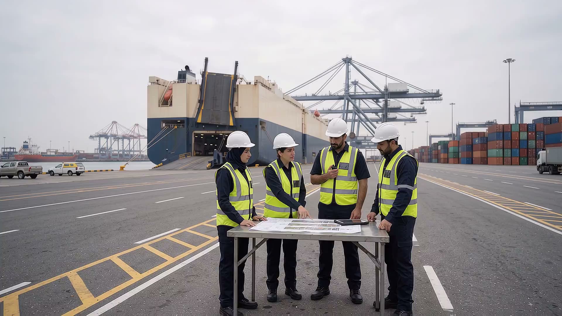
Step 1 of 9
Pre-Arrival Planning and Coordination

Execution sequence

  1. 1 Confirm ETA, berth, ramp position and cargo manifest.
  2. 2 Validate VIN list, model mix, exceptions and customs status.
  3. 3 Freeze manpower, radios, traffic route, parking zones and contingency plan.

Control points

  • Approved deck and discharge plan
  • Joint toolbox talk and communication matrix
  • Yard capacity and emergency lanes confirmed
Discharge sequence Stage 1 of 9
Next → 2 · Discharge Sequence Planning
4

Discharge Sequence Planning

Convert the vessel stow plan into a safe, uninterrupted lane-by-lane release.
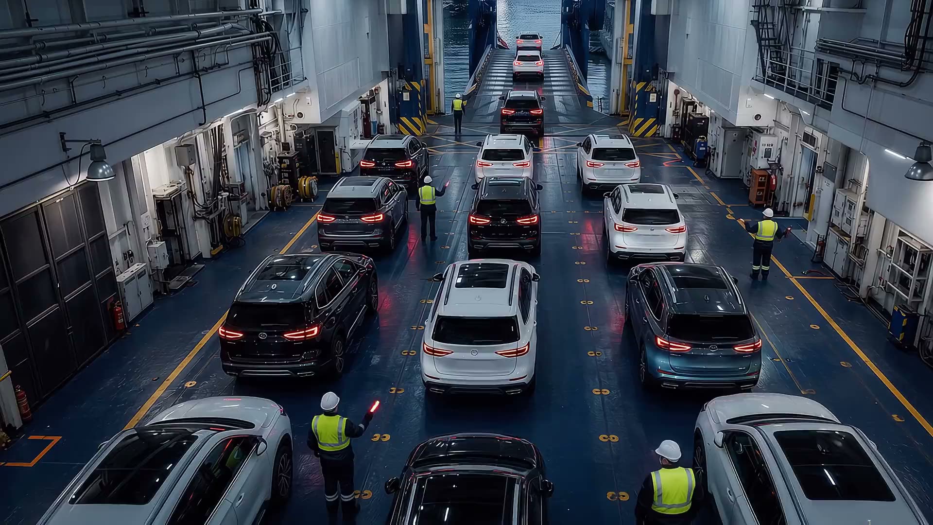
Step 2 of 9
Discharge Sequence Planning

Execution sequence

  1. 1 Prioritize ramp-accessible lanes and destination blocks.
  2. 2 Match deck release rate to inspection and yard absorption.
  3. 3 Mark non-runners, damaged units and special handling cargo.

Control points

  • Master sequence issued by deck and terminal control
  • No cross-flow between active lanes
  • Hold points used to prevent yard congestion
Discharge sequence Stage 2 of 9
Next → 3 · Cargo Unlashing Operations
5

Cargo Unlashing Operations

Release only the vehicles scheduled for immediate movement.

Step 3 of 9
Cargo Unlashing Operations

Execution sequence

  1. 1 Supervisor authorizes the active lane.
  2. 2 Remove straps, chains and wheel chocks completely.
  3. 3 Clear securing gear from the driving path before driver entry.

Control points

  • Continuous supervision
  • Only discharge or shift units are unlashed
  • Positive confirmation that all restraints are removed
Discharge sequence Stage 3 of 9
Next → 4 · Vessel Cargo Discharge
6

Vessel Cargo Discharge

Move vehicles from deck to quay under marshal control and controlled speed.
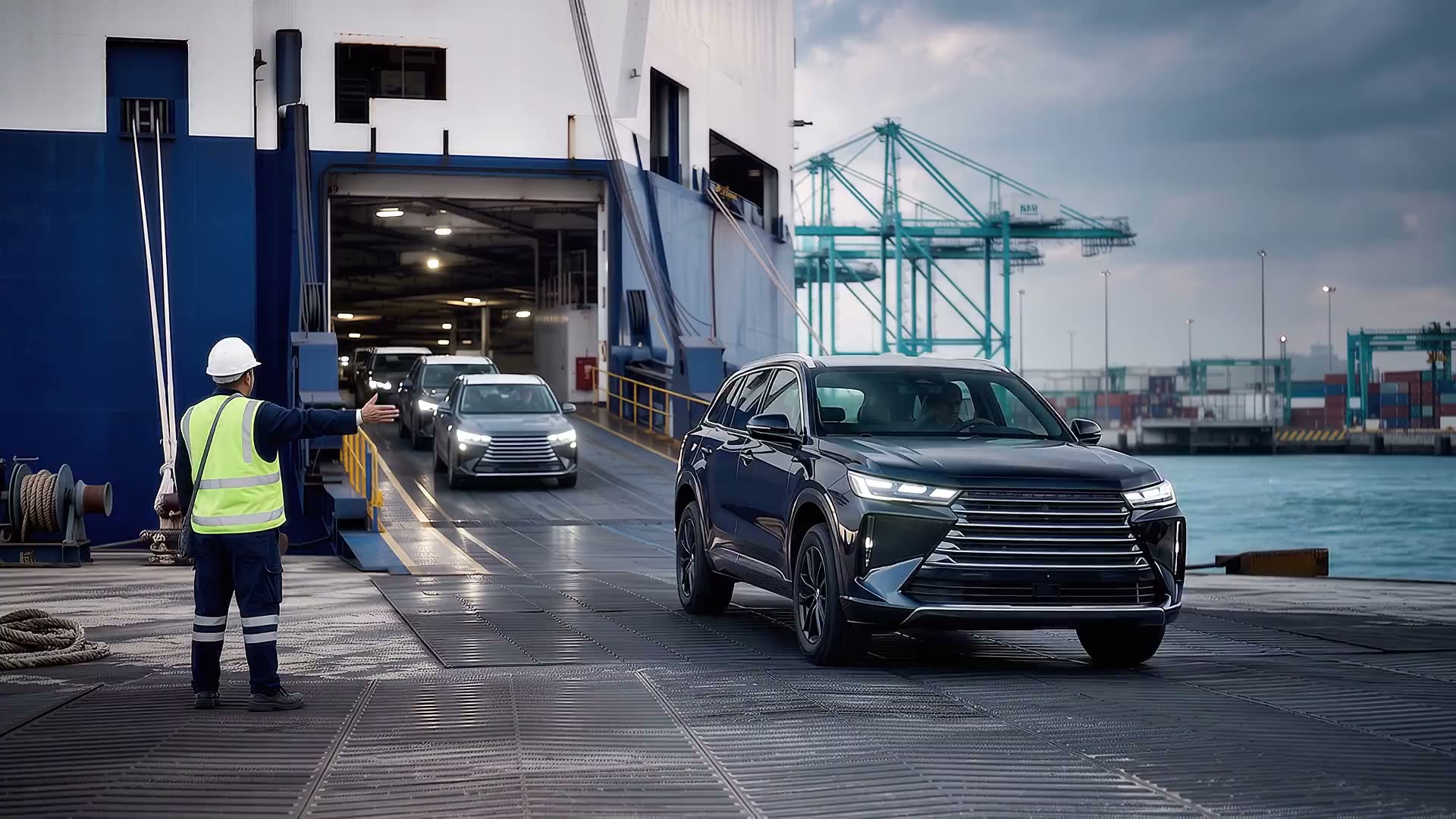
Step 4 of 9
Vessel Cargo Discharge

Execution sequence

  1. 1 Driver performs quick start, brake and steering check.
  2. 2 Follow marshal signals and designated ramp lane.
  3. 3 Maintain safe spacing; stop immediately on loss of communication.

Control points

  • Dedicated ramp marshal and signal system
  • Seat belt on, lights as instructed, no mobile phone
  • Defects and non-runners diverted to exception process
Discharge sequence Stage 4 of 9
Next → 5 · Initial Inspection and VIN Scanning
7

Initial Inspection and VIN Scanning

Create the first port-side condition and identity record.
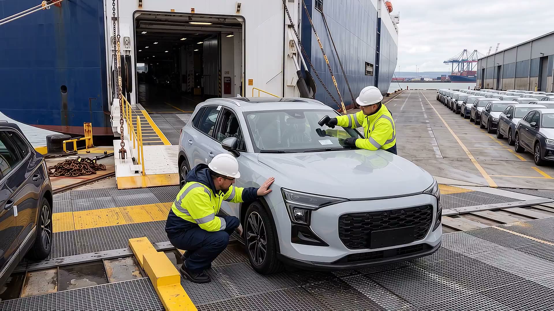
Step 5 of 9
Initial Inspection and VIN Scanning

Execution sequence

  1. 1 Scan VIN against discharge manifest.
  2. 2 Conduct a rapid 360° visual damage inspection.
  3. 3 Photograph and segregate mismatches or fresh damage.

Control points

  • VIN match before yard release
  • Timestamped exception evidence
  • Fast lane for clean units; quarantine lane for exceptions
Discharge sequence Stage 5 of 9
Next → 6 · Yard Parking and Marshalling
8

Yard Parking and Marshalling

Place each vehicle once, in the correct block, with safe one-door access.

Step 6 of 9
Yard Parking and Marshalling

Execution sequence

  1. 1 Marshal directs vehicle to assigned zone and bay.
  2. 2 Park straight within markings with controlled side clearance.
  3. 3 Switch off engine and lights; close windows, mirrors and doors as instructed.

Control points

  • One-way circulation and pedestrian separation
  • Keys and vehicle status controlled
  • No random parking or unrecorded relocation
Discharge sequence Stage 6 of 9
Next → 7 · Final Inspection, VIN Scan and Location Record
9

Final Inspection, VIN Scan and Location Record

Close the discharge transaction with verified identity, condition and precise bay location.
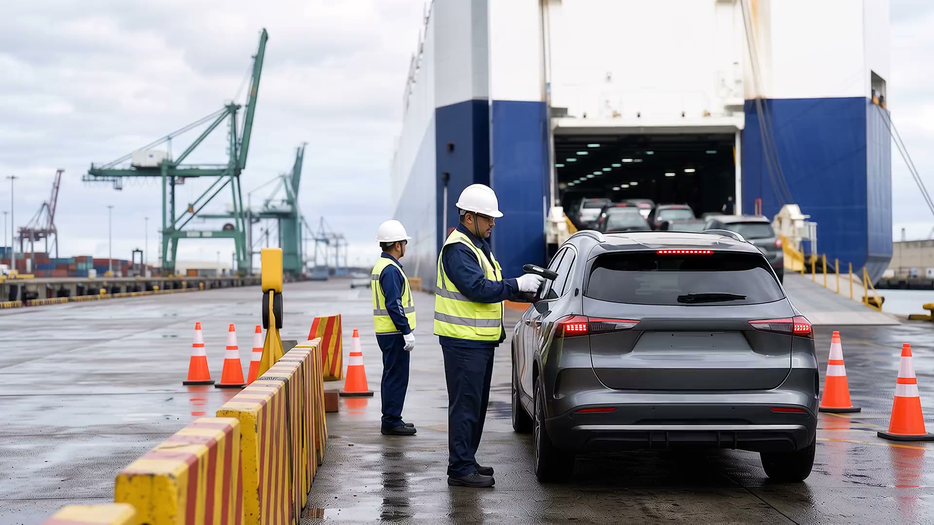
Step 7 of 9
Final Inspection, VIN Scan and Location Record

Execution sequence

  1. 1 Complete final condition check.
  2. 2 Rescan VIN and confirm the unit record.
  3. 3 Record zone, row and bay in the terminal system.

Control points

  • 100% VIN-to-location accuracy target
  • Damage exceptions linked to evidence
  • Inventory dashboard updated in real time
Discharge sequence Stage 7 of 9
Next → 8 · Customs Clearance Process
10

Customs Clearance Process

Release only vehicles with complete documentation and customs authorization.
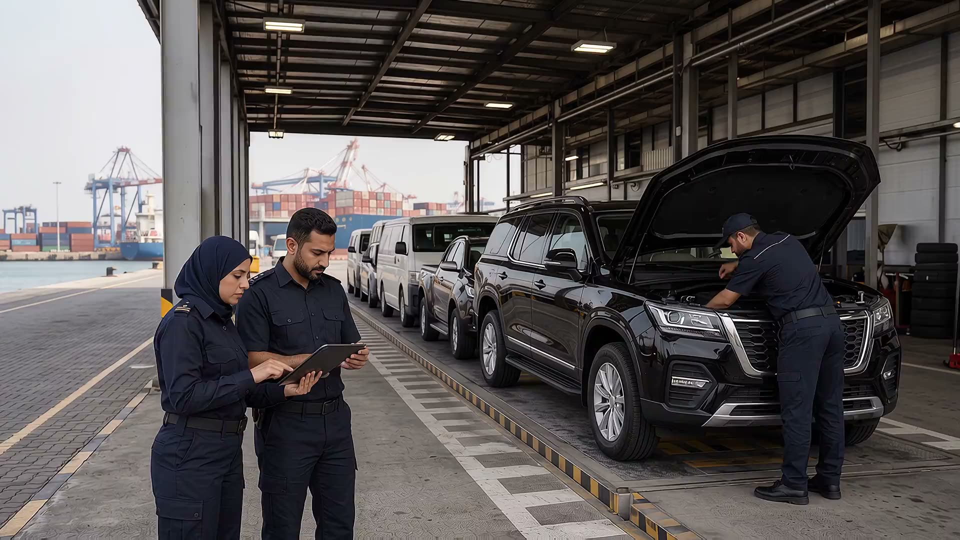
Step 8 of 9
Customs Clearance Process

Execution sequence

  1. 1 Reconcile manifest, VIN and clearance documents.
  2. 2 Present selected units for inspection when requested.
  3. 3 Update status from customs hold to released.

Control points

  • Secured customs hold area
  • No physical release without system authorization
  • Exception log for document or identity mismatch
Discharge sequence Stage 8 of 9
Next → 9 · Cargo Delivery and VIN Verification
11

Cargo Delivery and VIN Verification

Hand over the correct cleared vehicle to the authorized consignee or transporter.

Step 9 of 9
Cargo Delivery and VIN Verification

Execution sequence

  1. 1 Verify release order and transporter authorization.
  2. 2 Scan VIN at the delivery gate.
  3. 3 Capture handover time, condition and receiver acknowledgement.

Control points

  • Three-way match: VIN, release order, receiver
  • Final gate condition check
  • System status changed to delivered
Discharge sequence Stage 9 of 9
Next → KPI and manpower calculation
12

KPI and manpower calculation

At an eight-minute cycle, 34 drivers per shift provide a calculated 5,100 vehicles in 20 hours — a 2% margin above target.

Target
5,000
cars / 20 h
Cycle time
8
min / car
Drivers
68
34 per shift
Planned output
5,100
cars / 20 h

Shift calculation · resource planning

34 drivers × 600 min ÷ 8 min/car

= 2,550 cars per 10-hour shift

Two shifts: 2,550 × 2 = 5,100 cars

Capacity buffer

100 cars
2.0% above target
06,000 cars / 20 h

Operational note: breaks, driver transfers, congestion and exceptions can consume this buffer. Maintain relief coverage and live hourly control.

13

Hourly production control

Maintain the planned 255-car hourly run rate and track cumulative output against the shift target.

Control line · 255 cars / h
Shift target · 2,550 cars
255
255
510
255
765
255
1,020
255
1,275
255
1,530
255
1,785
255
2,040
255
2,295
255
2,550
255
12345678910
Shift operating hour Figures above bars are the cumulative count due by the end of that hour.
Escalation trigger

if any hour falls below 255, recover within the next hour through lane balancing, relief drivers or bottleneck removal.

14

Yard capacity and delivery plan

Ten receiving boxes support the discharge through planned storage and coordinated gate-out.

Allocated parking plan

3,990 positions

10 boxes × 7 rows × 57 cars

46,374 m² in receiving boxes · Including central corridor

Storage allocation covers 79.8% of the discharge target at one time.

Allocation by receiving section

SectionBoxesPositions
1–331,197
4–52798
6–72798
8–1031,197
Total103,990
Concurrent delivery requirement

At least 1,010 vehicles must clear the gate during the 20-hour discharge window.

Based on zero opening inventory. Add any opening stock to this requirement and keep occupancy within the 3,990-position allocation throughout the operation.

Planning basis: 4.1 m compact cars, 4.4 × 2.6 m bay pitch and lane-order release. Box area is model-derived and excludes outer spines, cross roads and unused margins. Confirm cargo dimensions and access clearances before operation.

15

Operating governance and stop-work controls

Protect the vehicle, the person and the record at every handoff.

Before start

1
  • Joint toolbox talk completed
  • Radios and channels tested
  • Routes, zones and emergency lanes open

During discharge

2
  • Ramp and deck under marshal control
  • Hourly KPI and queue levels monitored
  • Damage, VIN and non-runner exceptions segregated

Before delivery

3
  • Customs release status verified
  • VIN, location and condition records complete
  • Authorized receiver and gate handover captured
Stop work — any one of these
Hold the lane, confirm clear, then resume only on the supervisor's release.
unclear signalpedestrian in vehicle laneunsecured vehicleblocked rampunrecorded VIN mismatchunsafe speedloss of communications
16
1 / 1